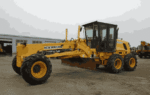
New Holland Rg140.B
New Holland Rg140.B Motor Grader Service Repair Manual
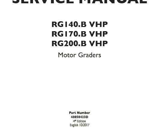
P. NB. 48050423
The manual covers:
General Maintenance
Troubleshooting
Engine Service / Repair
Wiring Diagram
Electrical System
Suspension
Periodic Lubrication
Fuel Injection
Hydraulics
New Holland Rg140.B Motor Grader Service Manual Wiring Diagram
Importance of the Service Wiring Diagram
The service wiring diagram for the New Holland Rg140.B motor grader serves as a visual guide that illustrates the electrical system”s layout. This diagram provides essential information regarding connections, wiring paths, and electrical component locations. Having access to a clear and accurate wiring diagram is beneficial for technicians who perform repairs or routine maintenance on the machine.
Key Features of the Wiring Diagram
The wiring diagram includes detailed representations of various circuits, making it easier to troubleshoot issues that may arise during operation. Key features include color-coded wires, clear labels of components, and indications of voltage readings. When dealing with complex electrical systems, as found in the New Holland Rg140.B, this documentation becomes invaluable in ensuring efficient service and repair procedures.
- General Machine Information and Safety Guidelines
- This section provides machine identification data, serial number locations, safety precautions, standard torque values, approved lubricants, and workshop practices required before servicing New Holland Rg140.B.
- Engine System and Mechanical Service
- Detailed coverage of diesel engine components, including fuel injection, air intake, cooling system, lubrication circuits, engine timing, mechanical tolerances, and inspection procedures for wear and performance issues.
- Hydraulic Drive and Vibration Systems
- Comprehensive servicing instructions for hydraulic pumps, motors, vibration assemblies, steering hydraulics, control valves, pressure testing, and hydraulic fault diagnostics.
- Transmission, Drum, and Propulsion Components
- Explains hydrostatic transmission operation, drum drive mechanisms, vibration exciter systems, bearings, seals, and alignment procedures critical to soil compaction performance.
- Electrical System and Diagnostic Procedures
- Includes wiring schematics, sensors, switches, control modules, starting and charging systems, and logical troubleshooting paths for electrical failures.
- Preventive Maintenance and Technical Specifications
- Covers maintenance intervals, fluid capacities, adjustment specifications, wear limits, inspection routines, and service schedules to ensure long-term reliability.
- Operational Troubleshooting and Fault Analysis
- Provides symptom-based diagnostic guidance for engine faults, hydraulic malfunctions, vibration issues, electrical problems, and operational irregularities commonly encountered in the field.