
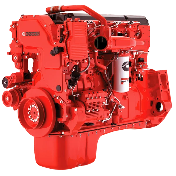
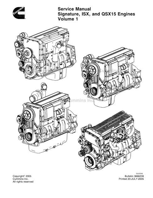
Cummins ISX QSX15 Engine Service Repair Manual
Jul
Cummins ISX QSX15 Engine Service Repair Manual
Specifications:
- Brand: John Deere
- Model: QSX15, ISX15
- Type: Cummins Diesel Engine Tier 4
- Manuals: Component Technical Manual
- Publication Numbers: CTM120219
- Language: English
- Format: PDF
In-Chassis Troubleshooting & Maintenance Guide
Product Overview
This official Cummins ISX and QSX15 Engine Service Repair Manual is the definitive technical resource for professional diesel technicians and fleet maintenance personnel. Specifically designed for in-chassis (on-vehicle) troubleshooting and repair, this manual provides step-by-step diagnostic procedures to identify and correct operational faults without requiring an initial engine tear-down.
For extensive overhauls, component rebuilding, and assembly clearances, this guide directs users to the complementary Engine Shop Manual. Developed by Cummins Inc. engineers, this publication ensures service accuracy, compliance with OEM standards, and operational safety, making it an essential asset for minimizing vehicle downtime and optimizing heavy-duty diesel performance.
Key Technical Specifications & Manual Details
| Specification | Detail |
|---|---|
| Applicable Engines | Cummins ISX (Industrial) & QSX15 (Marine/Industrial) – On-Highway and Off-Highway variants. |
| Service Scope | In-Chassis Repairs (Diagnostics, sensor testing, fuel system calibration, air handling, and electrical troubleshooting without removing the engine from the frame). |
| Associated Manuals | Engine Shop Manual (For full rebuilds), Specifications Manual, Alternative Repair Manual. |
| Safety Compliance | Adheres to General Safety Instructions and OEM WARNING protocols detailed in Section I. |
| Tooling Requirements | Specifies mandatory use of Cummins Special Service Tools (e.g., for injection timing, overhead adjustments). |
| OEM Part Support | Recommends use of Genuine Cummins or ReCon® exchange parts to guarantee longevity and warranty compliance. |
| Global Support | Contact your local Cummins Regional Office or call 1-800-DIESELS (U.S./Canada) for technical inquiries. |
| Format | Printable/PDF format with postage-paid Literature Survey Form for user feedback submissions. |
| Revision Status | Specifications based on information in effect at time of printing; subject to change without obligation. |
Comprehensive Manual Content Structure
The manual is logically sequenced to guide the technician from symptom recognition to final verification:
- Section i – Introduction: Instructions on how to navigate the manual, interpret abbreviations, and utilize safety warnings.
- Diagnostic Flowcharts: Logical, step-by-step decision trees for isolating faults.
- Sensor & Actuator Testing: Pinpoint tests for ECM inputs/outputs, including temperature, pressure, and position sensors.
- Fuel System Calibration: High-pressure common rail injection adjustments and leak-off tests.
- Air Intake & Exhaust Analysis: Turbocharger wastegate regulation, EGR valve operation, and DPF backpressure diagnostics.
- Lubrication & Cooling System Checks: Oil pressure verification, thermostat function, and water pump flow tests.
- Base Engine Mechanical Checks: Cylinder compression analysis, valve lash adjustments, and gear train inspection (in-chassis).
- Electronic Control Module (ECM) Diagnostics: Fault code interpretation and software parameter verification.
- Final Operational Tests: Post-repair performance validation and road-test parameters.
Specific Technical Issues & Repairs Covered (Nomenclature)
This manual is engineered to resolve common and complex operational failures. The exact technical aspects targeted for repair include:
- High-Pressure Fuel Injection Pump Timing and Calibration Errors – Correcting injector dwell time and rail pressure inconsistencies to resolve rough idling and power loss.
- Variable Geometry Turbocharger (VGT) Actuator Sticking or Feedback Failure – Repairing turbo response lag and over-boost conditions by testing the electronic actuator and unison ring.
- Engine Brake (Jake Brake) Solenoid and Valve Train Malfunctions – Diagnosing insufficient compression release braking performance due to hydraulic lash adjuster wear.
- Exhaust Gas Recirculation (EGR) Differential Pressure Sensor Drift – Identifying clogged venturi tubes causing excessive soot buildup and NOx emission failures.
- Crankcase Pressure Regulation Failures – Testing the breather assembly and CCV filter to prevent rear main seal oil leaks.
- Coolant Temperature Sensor Signal Intermittency – Resolving erratic temperature gauge readings that lead to false overheating alarms or poor fuel economy.
- Wiring Harness Chafing and Short-to-Ground Conditions – Pinpointing insulation breakdown in engine wiring looms that cause ECM communication interruptions (CAN bus errors).
- Injector Return Flow (Leak-Off) Volume Deviations – Measuring return fuel volumes to identify worn injector plungers causing misfires and white smoke on cold starts.
- Camshaft and Crankshaft Position Sensor Synchronization Drift – Relearning the cam-crank offset to prevent hard starting and engine shutdowns.
- Aftertreatment Diesel Particulate Filter (DPF) Soot Loading Estimation Errors – Correcting pressure sensor inaccuracies that trigger premature regeneration requests.
Related posts: